SAFE-FLEX INSIGHTS
ESD Workbench Setup: Specifying a Static-Safe Electronics Assembly Station
Specify an ESD-safe electronics workbench correctly. Covers frame materials, bench surfaces, M3 matting, grounding, and M4 floor coverage for UK assembly.
- static-safe-workbench-uk
- electronics-assembly-workbench
- esd-bench-specification
- epa-workbench-uk
ESD Workbench Setup: Specifying a Static-Safe Electronics Assembly Station
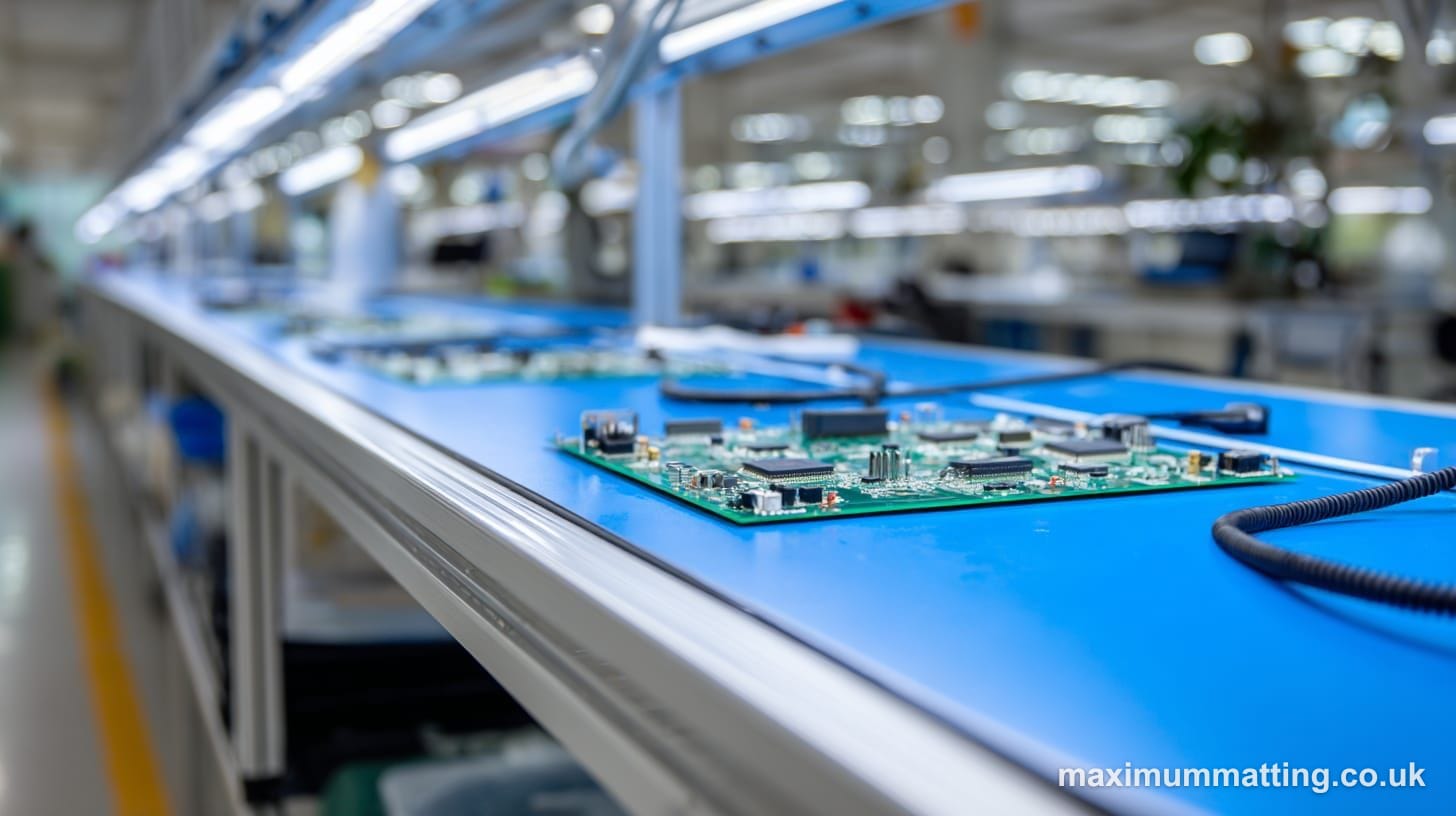
The bench surface is where most ESD damage happens. Not in transit, not in stores. It happens at the workstation, the moment a charged operator or tool contacts a sensitive component. Getting the workbench specification right before you order the matting saves rework and failed boards further down the line.
Why the workbench frame material matters
Steel-framed benches are inherently conductive. That is useful: you can bond the frame directly to earth via a dedicated stud, and any conductive surface layer on top becomes part of a continuous grounding path. The wrinkle is powder coating. Most steel benches are powder-coated, and the coating is insulative. When you fit the earth bonding stud, the coating needs to be broken at the contact point to achieve continuity. A star washer under the bolt usually handles this, but check it with a multimeter before assuming the bond is sound.
MDF and chipboard frames are non-conductive throughout. There is nothing wrong with using them in an EPA, but it means your grounding continuity depends entirely on the surface layer and the bench mat. The frame contributes nothing. If the mat is lifted or shifted mid-shift, grounding breaks.
Aluminium extrusion benches, popular in modular configurations, are conductive and can be bonded effectively. The same powder-coat caveat applies.
Whatever the frame, specify at least one dedicated M6 or M8 earth stud per workstation. Multi-station benches benefit from a grounding bar running the full length, with connection points at regular intervals. Fitting this during the initial build costs almost nothing. Retrofitting it into a live production bay costs considerably more.
Standard bench surfaces and why they fall short
Melamine-faced chipboard is the default surface on most off-the-shelf workbenches. Surface resistance is typically above 10^12 Ω, firmly in the insulative range. A PCB placed on that surface can hold a static charge indefinitely. When the operator picks it up, the discharge can exceed 100V even through normal handling. Many sensitive components fail at 10-20V.
Some bench suppliers label surfaces “anti-static.” That term is not controlled. Check the actual resistance figure in the data sheet. Some of these products are only marginally less insulative than standard melamine, and few reach the 10^6 to 10^9 Ω static-dissipative range required by IEC 61340-5-1 for EPA work surfaces. A surface resistance reading is the only meaningful test. The label is not.
ESD laminates bonded into the bench top are a better option when specified correctly, but they wear. The edges are particularly vulnerable, especially where components slide off the bench or where tool fixtures are bolted through the surface. Once resistance drifts above 10^9 Ω, the laminate is no longer performing its EPA function. Unlike a bench mat, you cannot easily replace it without effectively rebuilding the bench top.
Before committing to any bench top surface, it is worth measuring resistance with a surface resistance meter at several points across the area. Most facilities that have a meter use it only at commissioning. Measuring a new bench before the mat goes down gives you a useful baseline for comparison at future audits.
M3 bench matting as the surface layer
The practical solution for most UK electronics assembly operations is an ESD bench mat laid over the existing bench top. It provides a verified dissipative surface, can be removed for cleaning or replacement, and its resistance is measurable on-site with basic test equipment.
The M3 from Maximum Matting is rated at 10^6 to 10^9 Ω, the correct static-dissipative range for EPA work surfaces under IEC 61340-5-1. It is blue, which makes it visually distinct during audits and straightforward to photograph for EPA documentation records. Standard mats start from £23. Rolls are available cut to length per metre, which suits non-standard bench depths or continuous runs across multiple stations in a production bay.
A complete M3 workstation kit includes the mat, grounding cable, earth bonding plug, wrist strap, and heel grounder. That covers the full operator-to-earth grounding path in one order, without sourcing components from multiple suppliers.
Grounding: connecting mat, operator, and earth
The M3 mat connects to earth via a grounding cable running from the press-stud on the mat to an earth bonding plug in a standard 13A socket. The socket provides the earth pin only. No live circuit is involved. If the bench has a dedicated earthing stud, use that directly and skip the socket adaptor.
The wrist strap connects the operator to the same earth point. Wrist strap resistance (strap plus body plus earth connection) should read 750 kΩ to 35 MΩ with a calibrated tester. Test at the start of every shift, not just at commissioning. A wrist strap that passes one day can fail the next if the band has cracked or the press-stud connector is corroded.
The complete grounding setup process covers component selection, connection sequence, and what to record for audit. The principle is simple: every part of the operator-to-earth path needs to be tested and documented individually. Assuming the system is working because it was working last month is not sufficient.
When to add M4 floor matting
A wrist strap grounds the operator’s hands. It does not address charge building through the soles of their footwear while standing and shifting weight at a bench. If operators are on their feet rather than seated, a grounded floor surface in front of the workstation completes the EPA.
The M4 ESD floor mat, also rated at 10^6 to 10^9 Ω, sits directly in front of the bench. It is used alongside ESD footwear or heel grounders. Heel grounders are included in the M3 accessory kit, with accessories starting from £6. M4 floor mats start from £39.
Seated operators on chairs with anti-static castors are a slightly different scenario. The relevant question is always the same: is there a continuous grounding path from the operator’s body to earth at every point during the task? If the answer is not clearly yes, add a floor mat. The cost of getting this wrong is a warranty return or a production failure. Both cost considerably more than a £39 mat.
Tools, fixtures, and what sits on the bench mat
The M3 mat controls the primary work surface. Everything placed on it that can contact a sensitive component needs to be either grounded through the mat or made from ESD-safe materials. Soldering iron tips need to be earthed, with tip-to-earth resistance under 2 Ω. Standard plastic component bins are insulative and should be replaced with ESD trays or static-shielding bags. Component reels stored at the bench should sit in ESD-safe holders rather than cardboard boxes or standard plastic racks.
This part is frequently missed in workbench specifications. The mat and grounding kit handle the surface. The tools, holders, and storage items need a separate audit. Any item that is insulative and can contact a PCBA is a potential charge source, regardless of what it is sitting on.
A practical audit approach: stand at the bench and list everything within reach of an operator handling live components. Then check each item against a list of approved ESD-safe materials. Anything without a resistance figure in the dissipative range (10^6 to 10^9 Ω) or below should be replaced or removed from the EPA before the workstation goes live.
Documentation and periodic testing
IEC 61340-5-1 requires verification of EPA surfaces and personnel grounding at commissioning and at regular intervals thereafter. For most UK electronics facilities, annual surface resistance testing is the minimum for bench surfaces, with wrist strap testing at the start of each shift. Records need to be kept in a format that supports internal audit and any customer or third-party quality review.
The M3 mat’s resistance is stable across its service life, provided it is kept clean. Flux residue, solder paste, and general workshop contamination can shift surface resistance over time. Use an ESD-safe mat cleaner rather than standard IPA, which can leave residue depending on purity. For guidance on cleaning intervals and when a mat should be replaced rather than cleaned, the matting hygiene audit guide covers both triggers and schedules across different industrial surfaces.
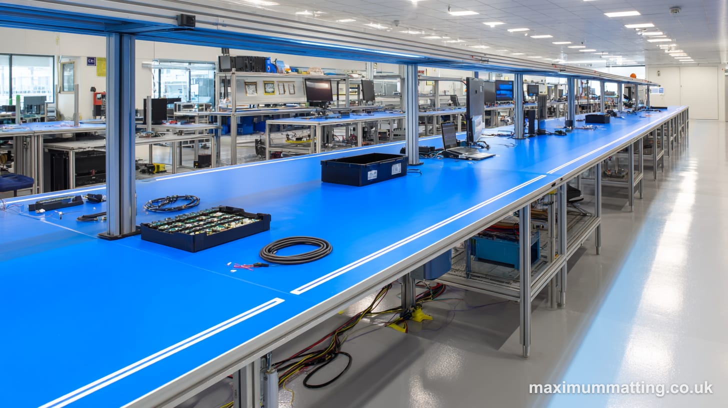
Planning a multi-bench layout
A single workstation is straightforward to specify. A production bay with ten or twenty benches involves decisions about common bonding network topology, grounding point locations relative to sockets, standing versus seated configurations per station, and whether roll matting or individual mats make better operational sense. These decisions affect cost, documentation workload, and how easily the layout can be reconfigured.
For that scale, a free site visit from Maximum Matting covers the groundwork: area measurement, grounding requirement confirmation, and a format recommendation per station. It is particularly useful when benches sit at varying depths or the floor surface under standing operators is uneven. No charge, no obligation.
Build your M3 basket online, or book a free site visit for multi-bench ESD layouts.
Free site visit
Get a Safe-Flex layout, slip data, and RAMS pack for your floor.
Book a free site visit and we’ll review hazards, measure the area, and specify the right modular matting. UK-manufactured from 100% recycled PVC compound.
Pressed in the West Midlands · 100% recycled PVC